Product Description
PROFESSIONAL MANUFACTURE
— SINCE 1995
High Torque NGW Series Cast Iron Planetary Gearbox for Conveyor
Chinese electric motor speed reducer is widely used in mining machinery, chemical industry,steel metallurgy, light
industry,environmental protection, paper making, printing, lifting transport, food industry and so on.
Main Series Product: R series helical gear motor reducer, K series spiral bevel gear reducer, NGW, P series planetary gear reducer, H B series helical gearbox, Z (ZDY, ZLY, ZSY, and ZFY) serial hard tooth surface cylindrical gearbox reducer, D (DBY and DCY) serial hard tooth surface cone gear reducer, cycloidal speed reducer, etc. Meanwhile, map sample processing business can be undertaken.
Product Description
Adopts modular design, which can be changed and combined according to customer requirements;
Adopts involute planetary gear transmission, uses internal and external meshing and power splitting;
The gears are all treated by carburizing and quenching to obtain a high-hard wear-resistant surface.
After heat treatment, the gears are all ground, which reduces noise and improves the efficiency and service life of the whole machine.
Light weight, small volume, large transmission ratio range, high efficiency, stable operation, low noise and strong adaptability.
Product Parameters
|
MODEL SIZE
|
RATIO RANGE
|
POWER
|
|
ONE STAGE
|
NGW
|
2.8 3.15 3.55 4 4.5 5 5.6 6.3 7.1 8 9 10 11.2 12.5
|
1.7-1228KW
|
|
TWO STAGE
|
NGW 122
|
22.4 .5 35.5 160
|
0.4-459KW
|
|
THREE STAGE
|
NGW 113 123
|
1800 2000
|
0.1-47.1KW
|
Model selection for washing machine Gear Box Transmission:
Closely using the ideal reduction ratio.
Reduction ratio = servo motor speed / reducer output shaft speed
Torque calculation: Torque calculation is very important for the life of reducer, and pay attention to whether the maximum torque value (TP) of acceleration exceeds the maximum load torque of the reducer.
The applicable power is usually the applicable power of the servo models on the market, the applicability of the reducer is very high, the working coefficient can be maintained above 1.2, but the choice can also be based on their own needs to decide. industrial helical gearbox.
Detailed Photos
Chinese Speed Reducer/industrial helical gearbox is a mechanical transmission in many fields of the national economy. The product categories covered by the industry include all kinds of gear reducer, planetary gear reducer and worm reducer, as well as various special transmission devices such as speed increasing device, speed control Devices, including various types of flexible transmission devices, such as compound transmission. Products and services in the field of metallurgy, nonferrous metals, coal, building materials, ships, water conservancy, electricity, construction machinery and petrochemical industries.
In all fields of national economy and national defense industry, gearbox products have a wide range of applications. Food light industry, electric machinery, construction machinery, metallurgy machinery, cement machinery, environmental protection machinery, electronic appliances, road construction machinery, water conservancy machinery, chemical machinery, mining machinery, conveyor machinery, building materials machinery, rubber machinery, petroleum machinery and other industries have strong demand of Reducer products
Packaging & Shipping
Application
| Driven machines |
| Waste water treatment |
Thickeners,filter presses,flocculation apparata,aerators,raking equipment,combined longitudinal and rotary rakes,pre-thickeners,screw pumps,water turbines,centrifugal pumps |
Dredgers |
Bucket conveyors, dumping devices, carterpillar travelling gears, bucket wheel excavators as pick up, bucket wheel excavator for primitive material, cutter head, traversing gears |
| Chemical industry |
Plate bending machines, extruders, dough mills, rubbers calenders, cooling drums, mixers for uniform media, agitators for media with uniform density, toasters, centrifuges |
Metal working mills |
plate tilters, ingot pushers, winding machines, cooling bed transfer frames, roller straigheners, table continuous intermittent, roller tables reversing tube mills, shears continuous, casting drivers, reversing CZPT mills |
| Metal working mills |
Reversing slabbing mills. reversing wire mills, reversing sheet mills, reversing plate mill, roll adjustment drives |
Conveyors |
Bucket conveyors, hauling winches, hoists, belt conveyors, good lifts, passenger lifts, apron conveyors, escalators, rail travlling gears |
| Frequency converters |
Reciprocating compressors |
| Cranes |
Slewing gears, luffing gears, travelling gears, hoisting gear, derricking jib cranes |
Cooling towers |
Cooling tower fans, blowers axial and radial |
| Cane sugar production |
Cane knives, cane mills |
Beet sugar production |
Beet cossettes macerators, extraction plants, mechanical refrigerators, juice boilers, sugar beet washing machines, sugar beet cutter |
| Paper machines |
Pulper drives |
Cableways |
Material ropeways, continuous ropeway |
| Cement industry |
Concrete mixer, breaker, rotary kilns, tube mills, separators, roll crushers |
|
|
Company Profile
Established in 1995 , HangZhou Boji Machinery is a professional manufacturer and exporter that is concerned with the design, development and production of Gearbox Speed Reducer. We are located in HangZhou of ZheJiang Province, with convenient transportation access. With our own brand “TianQi”, all of our products comply with international quality standards and are greatly appreciated in a variety of different markets throughout the world.
Our company possesses complete machining center, lathe, gear shaping machine, gear milling machine, gear grinding machine and assembling lines. Our well-equipped facilities and excellent quality control throughout all stages of production enables us to guarantee total customer satisfaction.
Besides, In 2005,we attained ISO9001 certification. As a result of our high quality products and outstanding customer service, we have gained a global sales network CZPT South America, Saudi Arabia, Vietnam, Pakistan, Philippines, South Africa and other countries and regions.
With rich export experience, high quality products, competitive prices, good service and in-time delivery, we certain that we can meet all of your requirement and exceed your expectations. Our feature is bright with new cooperative relationships with companies from all over the world. We look CZPT to speaking with you to future discuss how we can be of service to you.
FAQ
1. Who are we?
We are the Factory, with over 25 years of production experience, based in ZheJiang , China, start from 1995,sell to Domestic Market(50.00%),Mid East(10.00%),Southeast Asia(10.00%),Western Europe(5.00%),South America(5.00%),Eastern Europe(5.00%),Eastern Asia(5.00%),North America(3.00%),Africa(2.00%),Southern Europe(2.00%),South Asia(2.00%),Central America(1.00%).
2. Can you customize according to our requirements?
Yes, we can design nonstandard products according to customer’s drawing and sample.
3.What can you buy from us?
speed reducer,gearbox,gear motor,pump,crusher
4. Why should you buy from us not from other suppliers?
Founded in 1995, with over 20 years of production experience and credibility. With professional engineer team, advanced technology production and skilled workers.Specialized in the production of reducer. Map sample processing business can be undertaken.
5. What services can we provide?
Accepted Delivery Terms: FOB,CFR,CIF,EXW,DDP,DDU,Express Delivery;
Accepted Payment Currency:USD,EUR,JPY,CAD,AUD,HKD,GBP,CNY,CHF;
Accepted Payment Type: T/T,L/C,Credit Card,PayPal,Western Union,Cash;
Language Spoken:English,Chinese,Spanish,Japanese,Portuguese,German,Arabic,French,Russian,Korean,Hindi,Italian
| Application: |
Motor, Machinery, Manufacturing Plant |
| Hardness: |
Hardened Tooth Surface |
| Installation: |
Horizontal Type |
| Samples: |
US$ 1000/Piece
1 Piece(Min.Order)
|
Order Sample
High Torque NGW Series Cast Iron Planetary Gearbox
|
| Customization: |
Available
|
Customized Request
|
.shipping-cost-tm .tm-status-off{background: none;padding:0;color: #1470cc}
Shipping Cost:
Estimated freight per unit.
|
about shipping cost and estimated delivery time.
|
| Payment Method:
|
|
|
|
Initial Payment
Full Payment
|
| Return&refunds:
|
You can apply for a refund up to 30 days after receipt of the products.
|

The Cyclonoidal Gearbox
Basically, the cycloidal gearbox is a gearbox that uses a cycloidal motion to perform its rotational movement. It is a very simple and efficient design that can be used in a variety of applications. A cycloidal gearbox is often used in applications that require the movement of heavy loads. It has several advantages over the planetary gearbox, including its ability to be able to handle higher loads and higher speeds.
Dynamic and inertial effects of a cycloidal gearbox
Several studies have been conducted on the dynamic and inertial effects of a cycloidal gearbox. Some of them focus on operating principles, while others focus on the mathematical model of the gearbox. This paper examines the mathematical model of a cycloidal gearbox, and compares its performance with the real-world measurements. It is important to have a proper mathematical model to design and control a cycloidal gearbox. A cycloidal gearbox is a two-stage gearbox with a cycloid disc and a ring gear that revolves around its own axis.
The mathematical model is made up of more than 1.6 million elements. Each gear pair is represented by a reduced model with 500 eigenmodes. The eigenfrequency for the spur gear is 70 kHz. The modally reduced model is a good fit for the cycloidal gearbox.
The mathematical model is validated using ABAQUS software. A cycloid disc was discretized to produce a very fine model. It requires 400 element points per tooth. It was also verified using static FEA. This model was then used to model the stiction of the gears in all quadrants. This is a new approach to modelling stiction in a cycloidal gearbox. It has been shown to produce results comparable to those of the EMBS model. The results are also matched by the elastic multibody simulation model. This is a good fit for the contact forces and magnitude of the cycloid gear disc. It was also found that the transmission accuracy between the cycloid gear disc and the ring gear is about 98.5%. However, this value is lower than the transmission accuracy of the ring gear pair. The transmission error of the corrected model is about 0.3%. The transmission accuracy is less because of the lower amount of elastic deformation on the tooth flanks.
It is important to note that the most accurate contact forces for each tooth of a cycloid gearbox are not smooth. The contact force on a single tooth starts with a linear rise and then ends with a sharp drop. It is not as smooth as the contact force on a point contact, which is why it has been compared to the contact force on an ellipse contact. However, the contact on an ellipse contact is still relatively small, and the EMBS model is not able to capture this.
The FE model for the cycloid disc is about 1.6 million elements. The most important part of the FE model is the discretization of the cycloid disc. It is very important to do the discretization of the cycloid gear disc very carefully because of the high degree of vibration that it experiences. The cycloid disc has to be discretized finely so that the results are comparable to those of a static FEA. It has to be the most accurate model possible in order to be able to accurately simulate the contact forces between the cycloid disc and the ring gear.
Kinematics of a cycloidal drive
Using an arbitrary coordinate system, we can observe the motion of components in a cycloidal gearbox. We observe that the cycloidal disc rotates around fixed pins in a circle, while the follower shaft rotates around the eccentric cam. In addition, we see that the input shaft is mounted eccentrically to the rolling-element bearing.
We also observe that the cycloidal disc rotates independently around the eccentric bearing, while the follower shaft rotates around an axis of symmetry. We can conclude that the cycloidal disc plays a pivotal role in the kinematics of a cycloidal gearbox.
To calculate the efficiency of the cycloidal reducer, we use a model that is based on the non-linear stiffness of the contacts. In this model, the non-linearity of the contact is governed by the non-linearity of the force and the deformation in the contact. We have shown that the efficiency of the cycloidal reducer increases as the load increases. In addition, the efficiency is dependent on the sliding velocity and the deformations of the normal load. These factors are considered as the key variables to determine the efficiency of the cycloidal drive.
We also consider the efficiency of the cycloidal reducer with the input torque and the input speed. We can calculate the efficiency by dividing the net torque in the ring gear by the output torque. The efficiency can be adjusted to suit different operating conditions. The efficiency of the cycloidal drive is increased as the load increases.
The cycloidal gearbox is a multi-stage gearbox with a small shaft oin and a big shaft. It has 19 teeth and brass washers. The outer discs move in opposition to the middle disc, and are offset by 180 deg. The middle disc is twice as massive as the outer disc. The cycloidal disc has nine lobes that move by one lobe per drive shaft revolution. The number of pins in the disc should be smaller than the number of pins in the surrounding pins.
The input shaft drives an eccentric bearing that is able to transmit the power to the output shaft. In addition, the input shaft applies forces to the cycloidal disk through the intermediate bearing. The cycloidal disk then advances in 360 deg/pivot/roller steps. The output shaft pins then move around in the holes to make the output shaft rotate continuously. The input shaft applies a sinusoidal motion to maintain the constant speed of the base shaft. This sine wave causes small adjustments to the follower shaft. The forces applied to the internal sleeves are a part of the equilibrium mechanism.
In addition, we can observe that the cycloidal drive is capable of transmitting a greater torque than the planetary gear. This is due to the cycloidal gear’s larger axial length and the ring gear’s smaller hole diameter. It is also possible to achieve a positive fit between the fixed ring and the disc, which is achieved by toothing between the fixed ring and the disc. The cycloidal disk is usually designed with a short cycloid to minimize unbalance forces at high speeds.
Comparison with planetary gearboxes
Compared to planetary gearboxes, the cycloidal gearbox has some advantages. These advantages include: low backlash, better overload capacity, a compact design, and the ability to perform in a wide range of applications. The cycloidal gearbox has become popular in the multi-axis robotics market. The gearbox is also increasingly used in first joints and positioners.
A cycloidal gearbox is a gearbox that consists of four basic components: a cycloid disk, an output flange, a ring gear, and a fixed ring. The cycloid disk is driven by an eccentric shaft, which advances in a 360deg/pivot/roller step. The output flange is a fixed pin disc that transmits the power to the output shaft. The ring gear is a fixed ring, and the input shaft is connected to a servomotor.
The cycloidal gearbox is designed to control inertia in highly dynamic situations. These gearboxes are generally used in robotics and positioners, where they are used to position heavy loads. They are also commonly used in a wide range of industrial applications. They have higher torque density and a low backlash, making them ideal for heavy loads.
The output flange is also designed to handle a torque of up to 500 Nm. Its rotational speed is lower than the planet gearbox, but its output torque is much higher. It is designed to be a high-performance gearbox, and it can be used in applications that need high ratios and a high level of torque density. The cycloid gearbox is also less expensive and has less backlash. However, the cycloidal gearbox has disadvantages that should be considered when designing a gearbox. The main problem is vibrations.
Compared to planetary gearboxes, cycloidal gearboxes have a smaller overall size and are less expensive. In addition, the cycloid gearbox has a large reduction ratio in one stage. In general, cycloidal gearboxes have single or two stages, with the third stage being less common. However, the cycloid gearbox is not the only type of gearbox that has this type of configuration. It is also common to find a planetary gearbox with a single stage.
There are several different types of cycloidal gearboxes, and they are often referred to as cycloidal speed reducers. These gearboxes are designed for any industry that uses servos. They are shorter than planetary gearboxes, and they are larger in diameter for the same torque. Some of them are also available with a ratio lower than 30:1.
The cycloid gearbox can be a good choice for applications where there are high rotational speeds and high torque requirements. These gearboxes are also more compact than planetary gearboxes, and are suitable for high-torque applications. In addition, they are more robust and can handle shock loads. They also have low backlash, and a higher level of accuracy and positioning accuracy. They are also used in a wide range of applications, including industrial robotics.


editor by CX 2023-11-08
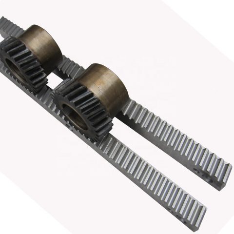 of gear rack
 PPS,PVDF.
 a mechanical gearbox which could be mounted within the vehicle?¡¥s transmission.
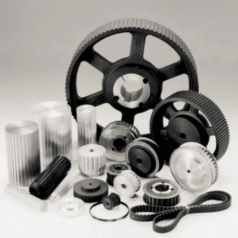 for taper bushing: 3V, 5V, 8V
  in addition with distinct attachment. Top quality can be assured!


